CAATO
Introduction
The CAATO is a small, nimble Autonomous Ground Vehicle (AGV) developed off of the LOCUST platform with more powerful and accurate motors and a patented (TBC) trolley docking mechanism. This platform will be the first-ever robot to be deployed under the Robotic middleware framework RMF 2.0 program and is developed in joint collaboration with Changi Airport.
Checkout the CAATO repository for more information: caato github
Operational WorkFlow
.png)
Autonomy
Introduction
The autonomy of the CAATO implementation consists of two main parts: navigation stack and computer vision intelligence.
A single board computer (SBC) and sagemaker is used to achieve the two parts. Currently both are running ROS Noetic with Ubuntu 20.04 setup.
Architecture
Major components of the overall system is shown below in the figure.
- NUC
- Perform mapping, localization, path planninig
- SageMaker
- Roboteq controller
- Perform BLDC motors control (closed loop speed control, i.e.
cmd_vel)
- Perform BLDC motors control (closed loop speed control, i.e.
- Pixhawk IMU
- Perform data fusion with odometry
- GPS location if outdoor
- Hokuyo LiDAR
- To perform 270 degree laser scan by combining one front-left LIDAR and one one right-rear LIDAR
- Ouster LiDAR (OS1-32)
- To perform 360 degree laser scan needed to carry out mapping and localization.
Software
General Operability & Overview
- For Caato2 to carry out its tasks using ROS, certain commands are needed to be executed
- Various packages are available to be implemented onto Caato2
-
Git Clone from
-
Packages and Launch Files
-
Caato2_bringup
- Launches certain relevant nodes which are needed for basic operation and functionality
- Roboteq Differential Driver - Control the motors
- Lasers - Activates the lasers used by Caato2
- Teleop - Enable manual control of Caato2
- DS4 Driver - Enable control of Caato2 using a remote joystick
- Launches certain relevant nodes which are needed for basic operation and functionality
-
Caato2_navigation
- Launches relevant stacks needed for navigation
- EBAND (Preferred)
- DWA
- TEB
- Launches relevant stacks needed for navigation
-
Cartographer (2D & 3D)
- Cartographer is a system that provides real-time simultaneous localization and mapping (SLAM) in 2D and 3D across multiple platforms and sensor configurations.
- For detailed tutorials on Cartographer implementation with ROS please go to the following link.
Cartographer ROS Integration - Cartographer ROS documentation
-
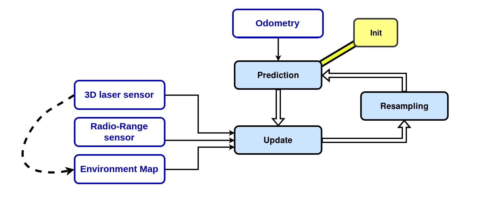
AMCL3D
- Adaptive Monte-Carlo Localization in 3D is a particle filter that allows you to estimate where a robot is within a 3D environment without using GPS, for example in indoor environments.
- The algorithm uses radio-range sensors, laser sensors, and a known map of the environment for calculating the particles weights. The algorithm takes as inputs an odometry, point-clouds that the robot sees and the distances between range sensors that are in the environment. It compares the map point-cloud with the robot point-clouds and takes into account the radio-range measurements to calculate the probability that the robot is in a bounded environment. In such environment, the particles have different weights according to each computed probability. The weighted average of all the particles would give the result of the robot pose (position and orientation).
-
Octomap
-
Xnergy charger
- roslaunch xnergy_charger_rcu xnergy_charger_modbus.launch
- Launches the modbus communication between the charger and the RCU
- rosservice call /xnergy_charger_rcu/start_charging
- Initiates the charging process
- roslaunch xnergy_charger_rcu xnergy_charger_modbus.launch
RViz
- RViz is a 3D visualization software tool for robots, sensors, and algorithms. It enables you to see the robot’s perception of its world (real or simulated). The purpose of RViz is to enable you to visualize the state of a robot. It uses sensor data to try to create an accurate depiction of what is going on in the robot’s environment
Gazebo
- Gazebo is a 3D robot simulator. Its objective is to simulate a robot, giving you a close substitute to how your robot would behave in a real-world physical environment. It can compute the impact of forces (such as gravity)
Mechanical
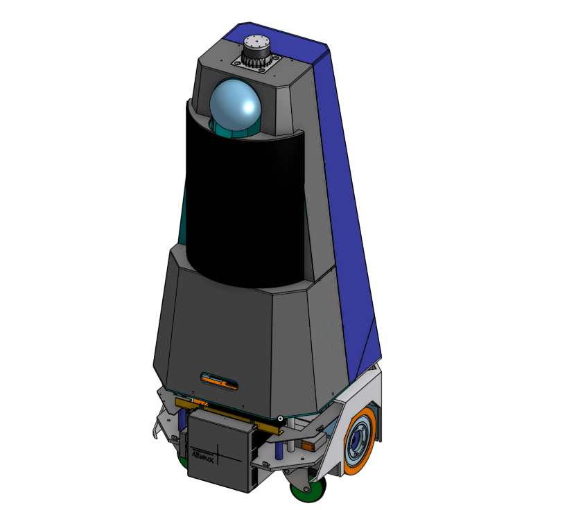
Full Assembly
Full assembly of Caato
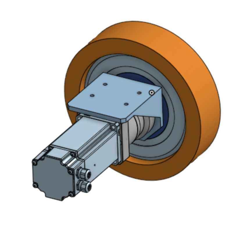
Drivetrain Assembly
Drivetrain Assembly of Caato
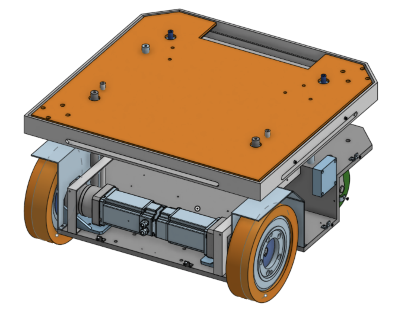
Chassis Assembly
Chassis Assembly of Caato
BOM
| Item No. | DWG No. | Part Description | Sub-assembly | Qty | Material | Finishing | Supplier |
|---|---|---|---|---|---|---|---|
| 1 | LC2_CS001 | Bottom Plate | Chassis | 1 | A5052 | NIL | Iron Man Fabrication |
| 2 | CTC Battery | Battery | Chassis | 1 | NIL | NIL | Xnergy |
| 3 | Xnergy_Receiver_Charging_unit | Battery Charging Unit | Chassis | 1 | NIL | NIL | Xnergy |
| 4 | LC2_CS013 | Rear cover | Chassis | 1 | A5052 | NIL | Iron Man Fabrication |
| 5 | Hinge | Hinge | Chassis | 2 | [Stainless Steel] SUS304 | NIL | Misumi |
| 6 | LC2_CS003 | LIDAR Plate | Chassis | 2 | A5052 | NIL | Iron Man Fabrication |
| 7 | LC2_CS004 | Xnergy Mount | Chassis | 2 | A5052 | NIL | Iron Man Fabrication |
| 8 | LC2_CS002 | Electronics Mounting Plate | Chassis | 1 | A5052 | NIL | Iron Man Fabrication |
| 9 | LC2_CS005 | Rear Payload Mounting Pillar | Chassis | 1 | A5052 | NIL | Iron Man Fabrication |
| 10 | LC2_CS006 | Fore Payload Mounting Pillar | Chassis | 1 | A5052 | NIL | Iron Man Fabrication |
| 11 | LC2_CS007 | Electronics Plate Pillar | Chassis | 1 | A5052 | NIL | Iron Man Fabrication |
| 12 | LC2_CS008 | Payload Plate | Chassis | 1 | A5052 | NIL | Iron Man Fabrication |
| 13 | LC2_CS009 | Wheel Well Cover | Chassis | 2 | A5052 | NIL | Iron Man Fabrication |
| 14 | LC2_CS011 | Fore LIDAR Plate Pillar | Chassis | 2 | A5052 | NIL | Iron Man Fabrication |
| 15 | LC2_CS010 | Rear LIDAR Plate Pillar | Chassis | 2 | A5052 | NIL | Iron Man Fabrication |
| 16 | HHPT7_b | Rear Access Panel Hinge | Chassis | 2 | [Stainless Steel] SUS304 | NIL | Misumi |
| 17 | HHPT7_p | Rear Access Panel Hinge | Chassis | 2 | [Stainless Steel] SUS304 | NIL | Misumi |
| 18 | LC2_CS012 | Rear Access Panel | Chassis | 1 | A5052 | NIL | Iron Man Fabrication |
| 19 | YWIB-V4E02R | E-stop button | Chassis | 1 | NIL | NIL | |
| 20 | LC2_CS015 | Cover Mount | Chassis | 13 | A5052 | NIL | Iron Man Fabrication |
| 21 | Castor Wheel | Castor Wheel | Chassis | 2 | Steel | Bright Chromate Plating | Misumi |
| 22 | 10:1 Gearbox | Gearbox | Drivetrain | 2 | NIL | NIL | Nidec |
| 23 | Motor | Motor | Drivetrain | 2 | NIL | NIL | Nidec |
| 24 | Wheel | Wheel attached to motor | Drivetrain | 2 | NIL | NIL | |
| 25 | Engineering Plastic Latch (with key) | For locking Rear Access Panel | Chassis | 3(?) | Plastic | NIL | Misumi |
| 26 | |||||||
| 27 | |||||||
| 28 | |||||||
| 29 | |||||||
| 30 | |||||||
Electricacl & Electronics
Table of Electronics
double check
| COMPONENT | MODEL NUMBER | # | PORTS | VOLTAGE RATING | MAX CURRENT DRAW | REMARKS |
|---|---|---|---|---|---|---|
| HOKUYO 2D LIDAR | UST-10LX | 2 | ETHERNET + POWER | 24 | ||
| PIXHAWK IMU/GPS | PIXHAWK 4 | 1 | USB | - | Connected to SBC | |
| REAL SENSE DEPTH CAMERA | D435 | 2 | USB | - | Connected to SBC | |
| ROUTER | AX11000 | 1 | POWER + ETHERNET | 12 | ||
| MIC-770 V2 (SBC) | 1 | POWER | 19 | Might change | ||
| PLC | CX9020EL1809EL2809EL3681x2EL6022EL7332 | 1 | POWER + ETHERNET+RS485 | 24 | ||
| LEISHEN 3D LIDAR | C16-700B | 1 | POWER + ETHERNET | 12 | ||
| DREAMVU 360 CAMERA | PAL USB | 1 | USB | - | Connected to SBC | |
| WHEEL MOTOR + ROBOTEQ | SBL3260T | 2 | POWER + ENCODER + HALL SENSORS+RS485 | 24 | ||
| LIFTING MOTOR | 24V DC MOTOR | 1 | POWER+BRAKE | 24 | ||
| JETSON | ||||||
| INFRARED SENSOR | GP2Y0A21YK | 2 | POWER+ANALOG OUT (JST terminal) | 5 | ||
| LASER BREAK SENSOR | EE-SX 674 | 2 | POWER + ANALOG OUT | 5 | ||
| E-STOP BUTTON | AVW411-R | 1 | 1NC1NO | -- | ||
| KARTECH E-STOP | 3A4663 | 1 | POWER+DIG OUTx2 | 9-30V | ||
| FORCE RESISTOR | FSR MODEL 408 34-23845 | 6 | VIN + VOUT | -- | Might Change | |
| DC-DC SOLID STATE RELAY | 1DD220D25 | 1 | VIN +VOUT, VCONTROL + GND | <220V, 3-32V | 25A | Between PLC and Roboteq Supply |
Power Diagram and Schematics
double check add in extra stuff
CAATO is powered by two 24V batteries (28.4V at full charge) in parallel, connected to a Xnergy receiver unit for wireless charging. The power is separated into two distinctions, propulsion and electronics.
The propulsion line provides power to the drive motor through the RoboteQ SBL3260T module, and is protected by a dedicated fuse, fly-back diode and various switches.
To cater to the different electronics, three voltage buses are provided by different DC-DC regulators (12V, 19V and 24V). The electronics line is protected by a single 10A fuse and placed in series with a switch, before being regulated at the various voltages. Each voltage bus is also connected to a switch then to individual terminal blocks for greater control and safety over the components.
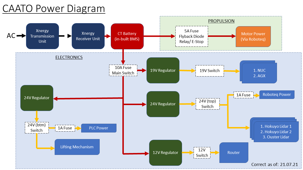
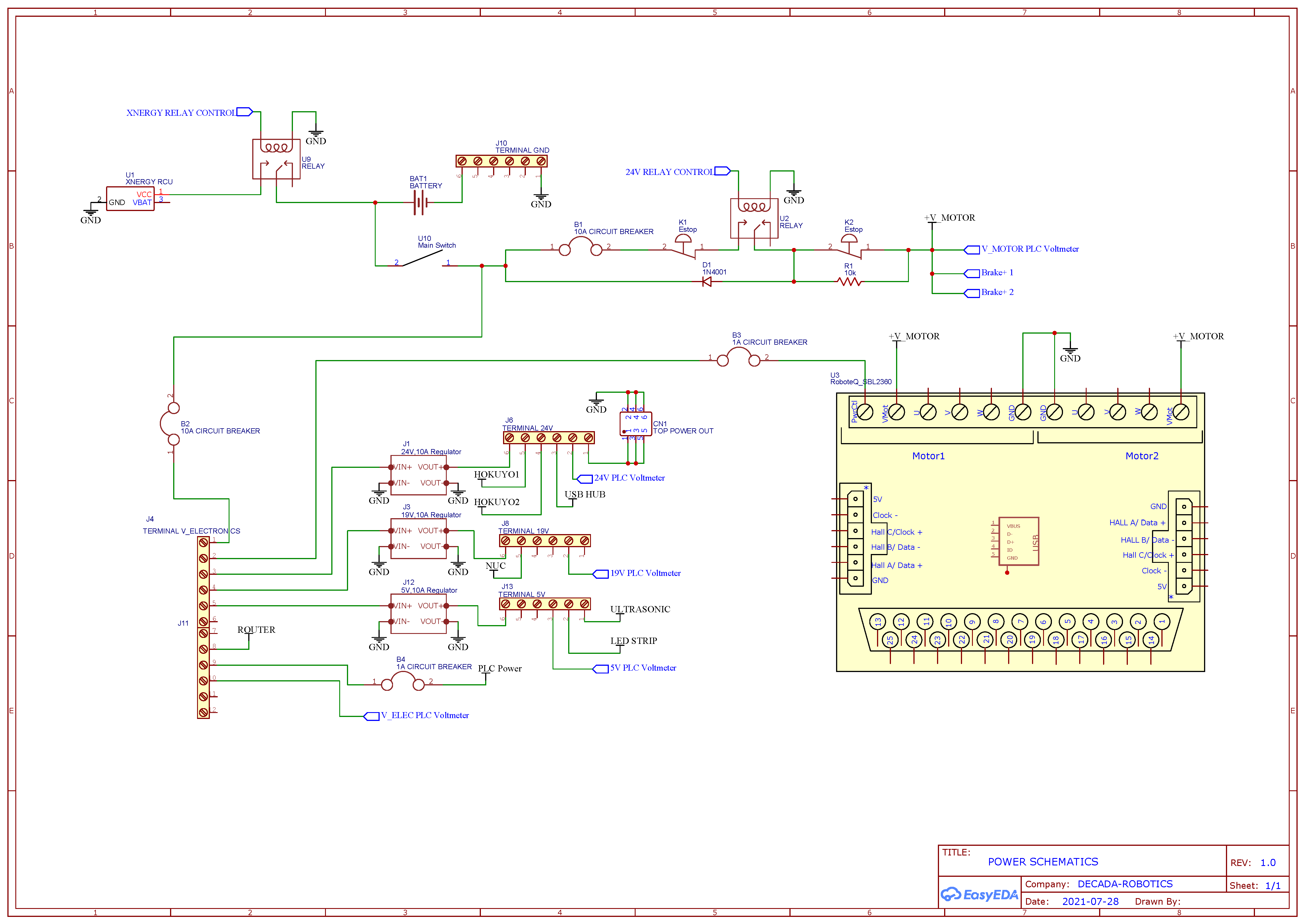
CAATO Power Schemetic
Programmable Logic Controller (PLC)
A programmable logic controller (PLC) was added for the second iteration of CAATO. Currently, we are using an Allen Bradley Micro820 . We intend for the PLC to satisfy 3 main objectives.
- Safety Layer - In the event the x86 computing layer experiences failure, the PLC will take over to bring the robot to a safe state. Two critical areas of concern are motion and battery power. For the former, all motion commands are forwarded through the PLC to ensure no additional movements are given in the event of emergency. For the latter, the flow of power from the battery and Xnergy charger are controlled from the PLC.
- Actuator Control - The PLC’s power, ruggedness and expandable I/O provide advantages over a basic microcontroller. We intend for the PLC to take over control of the trolley lift arm, which is currently operated by an Arduino Uno.
- Machine Interface and Status Monitoring - The PLC will act as a central control hub, monitoring the status of electronics and the individual voltage terminals. This information will be displayed on an LCD touchscreen for quick troubleshooting and testing.
Software
The software that we are using for our Allen Bradley Micro820 is Connected Components Workbench. To learn how to use this software check out.
Connected Components Workbench Software Tutorials
Other Peripherals
CAATO Arm
Hardware
Photomicro Sensor
We used 2 pairs of photomicro sensors, one to detect if the arm is lifted to the top, and one to detect if the arm is at the bottom.
Each pair consists of an emitter and a detector. When the arm is moved into the top or bottom position, it will block the laser beam coming from the respective emitter, and its corresponding detector will detect a decrease in optical energy. An output signal will then be sent to the arduino microcontroller.
There are 4 wires connected to each sensor.
- Brown: live
- Black: output
- Blue: ground
- White: not in use
Breakbeam Sensor
2 pairs of breakbeam sensors were used to detect the docking status of the trolley. They work in a very similar fashion to the photomicro sensors mentioned in the previous paragraph.
If the trolley is properly engaged by the arm, the laser beam from the emitter will be blocked and cannot reach the detector. The sensors will then output a “FALSE” value.
We placed one pair of breakbeam sensors on each side of the arm. In order for the trolley to be considered successfully docked, the breakbeam sensors on both sides must return a “FALSE” value. If the laser beam from only one, or neither, pair of breakbeam sensors is blocked, the trolley is considered incorrectly docked, and the arm will be lowered back to the bottom position for the robot to re-attempt the docking action.
There are 3 wires connected to each detector (but only 2 for each transmitter, which lacks a signal wire).
- Black: ground
- Red: live
- White: signal (see “Arduino” section below for wiring information)
Arduino
The arduino is used to check the output from the sensors and provide input to the dc motor driver.
In our current implementation of CAATO2, the wiring of the various signal pins is as follows:
- 4: Top photomicro sensors
- 6: Bottom photmicro sensors
- 7: Breakbeam sensor 1
- 12: Breakbeam sensor 2
DC Motor Driver
The motor driver is used to check inputs from the arduino and provide output to the linear motor. We give a 24V input to the dc motor driver. We power the arduino through the 5v regulator from the dc motor driver.
Stripboard
We used the stripboard to connect the sensors to the arduino.
After seeing all the codes, all the pinouts will make much more sense.
Software
check out the repository for caato arm at https://github.com/TRL-RMF/bb_ros
LED Strip
The circuit is set up as shown in the diagram below, with a 330Ω resistor to reduce data reflections and a 470µF capacitor to reduce voltage spikes on startup and shutdown.
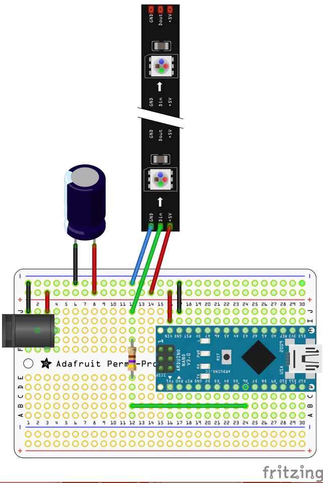
Available commands:
“RED.”, “BLUE.”, “GREEN.”, “WHITE.”, “PURPLE.”, “OFF.”.
Attached is the updated code, LED_control_100821.ino
Amazon Alexa
LED Panel
Roboteq and Motor Tuning
BOM
Deployment & Operation Concerns
3D Mapping
3D Mapping Notes
1. Initial Mapping
In order to start mapping, we need to run the mapping launch file and simultaneously record rosbag
Example of such mapping launch file:
<launch>
    <!-- <include file="$(find caato2_bringup)/launch/include/description_caato_3d.launch" /> -->

    <include file="$(find caato2_bringup)/launch/include/caato2_3d_lasers.launch" />

    <include file="$(find roboteq_diff_driver)/launch/driver.launch" >
    <arg name="base_frame" value="base_link"/>
    <arg name="pub_odom_tf" value="true"/>
    </include>

    <include file="$(find caato_teleop)/launch/ds4.launch" />

</launch>
After running the launch file, run rosbag record -a in another terminal.
After completing the mapping, kill the rosbag and followed by the launch file.
2. Obtaining the map
In this stage make use of offline cart node in google cartographer and pass the bag as an argument
The command would be:
roslaunch cartographer_ros offline_cart_3d.launch bag_filenames:="</path_to_bag>"
After the node completes cleanly, a .pbstream file will be created.
offline_cart_node.launch:
<launch>
  <param name="/use_sim_time" value="true" />

  <node name="rviz" pkg="rviz" type="rviz" required="true"
      args="-d $(find cartographer_ros)/configuration_files/demo_3d.rviz" />

  <node name="cartographer_offline_node" pkg="cartographer_ros"
      type="cartographer_offline_node" args="
          -configuration_directory $(find cartographer_ros)/configuration_files
          -configuration_basenames cart_3d.lua
          -urdf_filenames $(find cartographer_ros)/urdf/os1_sensor.urdf
          -bag_filenames $(arg bag_filenames)"
      output="screen">
    <remap from="points2" to="/os_cloud_node/points" />
    <remap from="imu" to="/os_cloud_node/imu" />
  </node>

  <node name="cartographer_occupancy_grid_node" pkg="cartographer_ros"
      type="cartographer_occupancy_grid_node" args="-resolution 0.05" />
</launch>
Remember you need to pass .lua configuration and the lidar sensor urdf files in the offline cart launch. The example of those files can be seen below:
cart_3d.lua:
include "map_builder.lua"
include "trajectory_builder.lua"

options = {
  map_builder = MAP_BUILDER,
  trajectory_builder = TRAJECTORY_BUILDER,
  map_frame = "map",
  tracking_frame = "os_imu",
  published_frame = "base_link",
  odom_frame = "base_link",
  provide_odom_frame = false,
  publish_frame_projected_to_2d = false,
  use_odometry = false,
  use_nav_sat = false,
  use_landmarks = false,
  num_laser_scans = 0,
  num_multi_echo_laser_scans = 0,
  num_subdivisions_per_laser_scan = 1,
  num_point_clouds = 1,
  lookup_transform_timeout_sec = 0.2,
  submap_publish_period_sec = 0.3,
  pose_publish_period_sec = 5e-3,
  trajectory_publish_period_sec = 30e-3,
  rangefinder_sampling_ratio = 1.,
  odometry_sampling_ratio = 1.,
  fixed_frame_pose_sampling_ratio = 1.,
  imu_sampling_ratio = 1.,
  landmarks_sampling_ratio = 1.,
}
-- Original defaults
TRAJECTORY_BUILDER_3D.num_accumulated_range_data = 1

MAP_BUILDER.use_trajectory_builder_3d = true
MAP_BUILDER.num_background_threads = 4

POSE_GRAPH.optimization_problem.huber_scale = 5e2
POSE_GRAPH.optimize_every_n_nodes = 320
POSE_GRAPH.constraint_builder.sampling_ratio = 0.03
POSE_GRAPH.optimization_problem.ceres_solver_options.max_num_iterations = 500
POSE_GRAPH.constraint_builder.min_score = 0.62
POSE_GRAPH.constraint_builder.global_localization_min_score = 0.66

-- Modifications
TRAJECTORY_BUILDER_3D.ceres_scan_matcher.translation_weight = 5.

TRAJECTORY_BUILDER_3D.use_online_correlative_scan_matching = true
TRAJECTORY_BUILDER_3D.imu_gravity_time_constant = .1

-- No point of trying to SLAM over the points on your cart.
TRAJECTORY_BUILDER_3D.min_range = 1.0
TRAJECTORY_BUILDER_3D.max_range = 50

-- These were just my first guess: use more points for SLAMing and adapt a bit for the ranges that are bigger for cars.
TRAJECTORY_BUILDER_3D.high_resolution_adaptive_voxel_filter.max_length = 5.
TRAJECTORY_BUILDER_3D.high_resolution_adaptive_voxel_filter.min_num_points = 250.
TRAJECTORY_BUILDER_3D.low_resolution_adaptive_voxel_filter.max_length = 8.
TRAJECTORY_BUILDER_3D.low_resolution_adaptive_voxel_filter.min_num_points = 400.

-- The submaps felt pretty big - since the car moves faster, we want them to be
-- slightly smaller. You are also slamming at 10cm - which might be aggressive
-- for cars and for the quality of the laser. I increased 'high_resolution',
-- you might need to increase 'low_resolution'. Increasing the
-- '*num_iterations' in the various optimization problems also trades
-- performance/quality.
TRAJECTORY_BUILDER_3D.submaps.high_resolution = .25
TRAJECTORY_BUILDER_3D.submaps.low_resolution = .60
TRAJECTORY_BUILDER_3D.submaps.num_range_data = 270
TRAJECTORY_BUILDER_3D.ceres_scan_matcher.ceres_solver_options.max_num_iterations = 50

-- Trying loop closing too often will cost CPU and not buy you a lot. There is
-- little point in trying more than once per submap.
MAP_BUILDER.pose_graph.optimize_every_n_nodes = 100
MAP_BUILDER.pose_graph.constraint_builder.sampling_ratio = 0.03
MAP_BUILDER.pose_graph.optimization_problem.ceres_solver_options.max_num_iterations = 200

MAP_BUILDER.pose_graph.constraint_builder.min_score = 0.5

-- Crazy search window to force loop closure to work. All other changes are probably not needed.
--MAP_BUILDER.sparse_pose_graph.constraint_builder.max_constraint_distance = 250.
--MAP_BUILDER.sparse_pose_graph.constraint_builder.fast_correlative_scan_matcher_3d.linear_xy_search_window = 250.
--MAP_BUILDER.sparse_pose_graph.constraint_builder.fast_correlative_scan_matcher_3d.linear_z_search_window = 30.
--MAP_BUILDER.sparse_pose_graph.constraint_builder.fast_correlative_scan_matcher_3d.angular_search_window = math.rad(60.)
--MAP_BUILDER.sparse_pose_graph.constraint_builder.ceres_scan_matcher_3d.ceres_solver_options.max_num_iterations = 50
os1_sensor.urdf
<robot name="os_sensor">
  <material name="orange">
    <color rgba="1.0 0.5 0.2 1" />
  </material>
  <material name="gray">
    <color rgba="0.2 0.2 0.2 1" />
  </material>

  <link name="os_imu">
    <visual>
      <origin xyz="0.0 0.0 0.0" />
      <geometry>
        <box size="0.06 0.04 0.02" />
      </geometry>
      <material name="orange" />
    </visual>
  </link>

  <link name="os_lidar">
    <visual>
      <origin xyz="0.0 0.0 0.0" />
      <geometry>
        <cylinder length="0.07" radius="0.05" />
      </geometry>
      <material name="gray" />
    </visual>
  </link>

  <link name="os_sensor" />

  <link name="base_link" />

  <!-- Legacy data -->
  <link name="os" />

  <joint name="os_link_joint_legacy" type="fixed">
    <parent link="base_link" />
    <child link="os" />
    <origin xyz="0.00 0. 0.03618" rpy="0. 0 0" />
  </joint>

  <joint name="sensor_link_joint" type="fixed">
    <parent link="base_link" />
    <child link="os_sensor" />
    <origin xyz="0 0 0" rpy="0 0 0" />
  </joint>

  <joint name="imu_link_joint" type="fixed">
    <parent link="os_sensor" />
    <child link="os_imu" />
    <origin xyz="0.006253 -0.011775 0.007645" rpy="0 0 0" />
  </joint>

  <joint name="os_link_joint" type="fixed">
    <parent link="os_sensor" />
    <child link="os_lidar" />
    <origin xyz="0.0 0.0 0.03618" rpy="0 0 3.14159" />
  </joint>

</robot>
3. Obtain PCD file
In order to obtain the PCD file, we make use of cartographer’s build in node called assets_writer_cart_3d.
The command is as follows:
roslaunch cartographer_ros assets_writer_cart_3d.launch
****bag_filenames:=${HOME}/Downloads/b3-2016-04-05-14-14-00.bag pose_graph_filename:=${HOME}/Downloads/b3-2016-04-05-14-14-00.bag.pbstream
This will be create a PCD file.
After obtaining the initial PCD file, it has to be down sampled in order to reduce the time it takes to create the .bt file in the next step.
The command is as follows:
pcl_voxel_grid <input>.pcd downsampled.pcd -leaf 0.05,0.05,0.05
A new down sampled .pcd file will be created.
4. Obtain BT file
To obtain BT file, we have to make use of octomap tracking server and pcdTopointcloud
The command for pcdTopointcloud launch is as follows:
roslaunch octomap_server pcdTopointcloud.launch
Remember to change the file name in the pcdTopointcloud.launch and build again
The command is as follows:
roslaunch octomap_server octomap_tracking_server.launch
Followed by octomap_saver
rosrun octomap_server octomap_saver -f <name_of_map>.bt octomap_full:=octomap_full
This will produce a .BT file
Octomap_tracking_server.launch sample code:
<launch>

  <arg name="path" default=""/>
  <arg name="changeIdFrame" default="/talker/changes"/>

    <!-- you can load an exisiting tree with <node ... args="tree.bt"> !-->
    <node pkg="octomap_server" type="octomap_tracking_server_node" name="octomap_talker"    output="screen" args="$(arg path)">
        <param name="resolution" value="0.05" />
        <param name="frame_id" type="string" value="map" />
        <param name="sensor_model/max_range" value="20.0" />
        <param name="save_directory" value="$(optenv OCTOMAP_SAVE_DIR ./)" />
        <param name="track_changes" value="true"/>
        <param name="listen_changes" value="false"/>
        <param name="topic_changes" value="/octomap_tracking_server/changeset" />
            <param name="change_id_frame" value="$(arg changeIdFrame)" />
            <param name="min_change_pub" value="0" />
            <param name="filter_ground" value="false" />
            <param name="pointcloud_max_z" value="0.5" />
            <param name="pointcloud_min_z" value="-0.7" />
            <param name="base_frame_id" value="base_link" />
        <!--remap from="cloud_in" to="/rgbdslam/batch_clouds" /-->
    </node>
</launch>
The most important arguments are:
- pointcloud_max_z
- pointcloud_min_z
- base_frame_id
5. Obtaining 2D map
This step is similar to step 4, but with changes to pointcloud_max_z and pointcloud_min_z in the tracking_server launch file. The changes are as follows
- pointcloud_max_z = 0.5
- pointcloud_min_z = -0.5
Then rerun the following command:
roslaunch octomap_server octomap_tracking_server.launch
🌟In this step, we will be making sure of the normal 2D map_saver instead of the octomap_server. Furthermore, change the topic that the server subscribes to from /map to /projected_map
Use the following command:
rosrun map_server map_saver map:=/projected_map -f name_of_map
Map.yaml and map.png files will be created.